How to Connect an Arduino Circuit
Short Answer:
The most common mistake when connecting an Arduino circuit is not understanding how the pins on a breadboard are connected.
On a breadboard, some pins are connected horizontally, others vertically, and the + / – power rails work separately.
Beginners often face problems like:
- “My circuit is not working”
- “The LED does not turn on”
- “The code is correct, but nothing happens”
This page explains:
- How a breadboard works
- How + and – power rails operate
- How horizontal and vertical connections are made
- The most common Arduino wiring mistakes
in a clear and beginner-friendly way.
What Is a Breadboard?
A breadboard is a solderless prototyping board that allows you to build electronic circuits without soldering.
It is used in almost every Arduino beginner project.
Using a breadboard:
- Components like LEDs, resistors, and sensors are easy to connect
- Mistakes can be fixed quickly
- The risk of damaging components is reduced
Breadboard Sections Explained
A standard breadboard has three main sections:
- Top power rails (+ / –)
- Bottom power rails (+ / –)
- Middle connection area (pin rows)
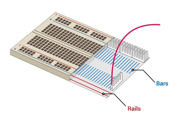
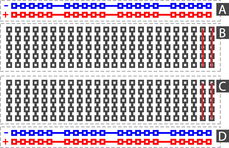
How Do + and – Power Rails Work?
The red (+) and blue (–) lines on the sides of the breadboard are called power rails.
- They are used to distribute power
- All holes on the same rail are electrically connected
- Arduino 5V and GND pins are usually connected here
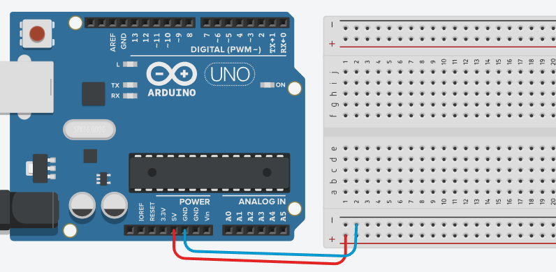
📌 Example:
- Arduino 5V → + rail
- Arduino GND → – rail
⚠️ Common mistake:
Assuming the top and bottom power rails are automatically connected
→ In most breadboards, they are NOT connected
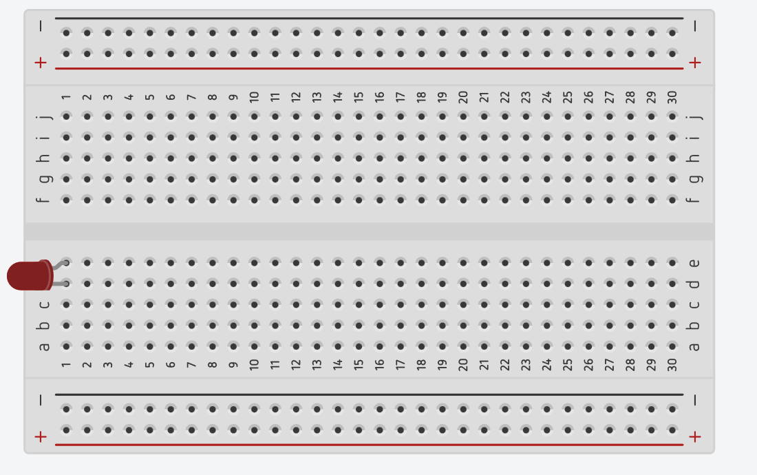
How Does the Middle Section Work? (Rows & Columns)
In the middle section of the breadboard, pins are connected horizontally.

As shown below, each horizontal row is internally connected.
Connection logic:
- The 5 holes in the same row are connected
- There is no vertical connection
- The center gap separates the left and right sides
📌 This means:
- Components placed in the same row are electrically connected
- Components in different rows are not connected
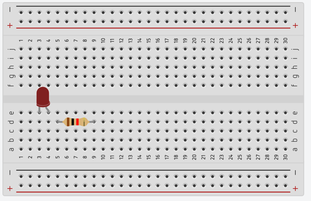
Most Common Arduino Breadboard Mistakes
❌ 1. Placing LED legs in the same row
➡ Creates a short circuit, the LED will not light up
❌ 2. Placing the resistor in the wrong row
➡ The circuit is not completed
❌ 3. Forgetting the GND connection
➡ The circuit will not work (very common)
❌ 4. Connecting + rail directly to – rail
➡ May damage the Arduino
❌ 5. Not realizing the power rail is broken
➡ Top rail works, bottom rail does not
❌ 6. Not understanding horizontal connections
➡ The middle section works horizontally, not vertically
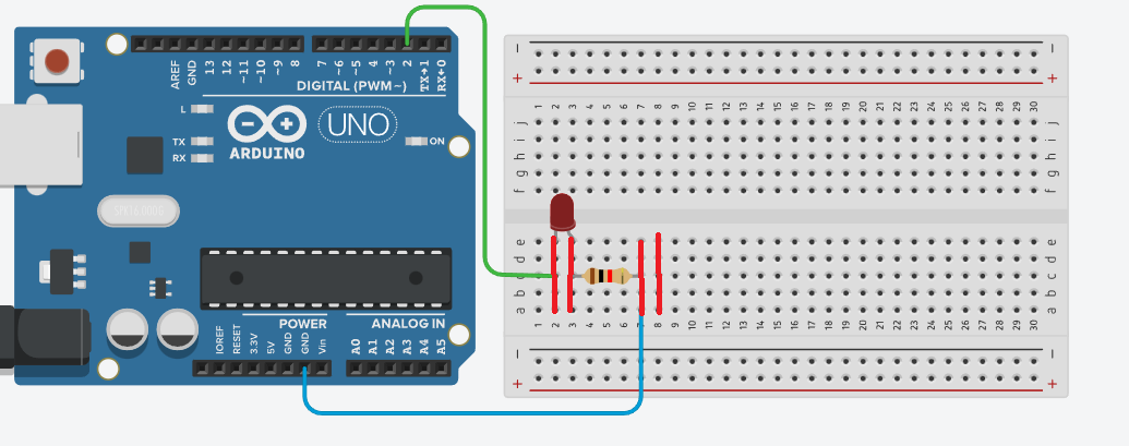
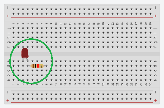
Each leg of a component must be placed in different rows.
Below is a correct LED + resistor connection example.
One leg of the LED and one leg of the resistor must share the same row to complete the circuit.
Arduino Circuit Not Working? Checklist
Quick Troubleshooting Checklist
- Is GND connected to the Arduino?
- Is the LED polarity correct (+ / –)?
- Is the resistor connected in series?
- Are the components in the correct rows?
- Are the + / – rails connected correctly?
Conclusion
The most common reason Arduino circuits fail is misunderstanding breadboard pin connections.
If horizontal connections or power rails are used incorrectly, the circuit will not work.
Once you understand how a breadboard works:
- Circuit building becomes faster
- Hardware errors are minimized
- Arduino projects become more reliable and enjoyable
👉 A successful Arduino project always starts with
correct breadboard wiring.